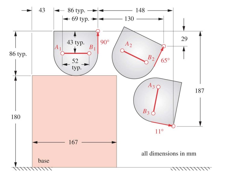
Problem 3-54, page 165 in textbook.
Design a four-bar linkage to move the object in Figure P3-15 through the three positions shown using
points A and B for attachment. Add a non-quick-return driver dyad to limit its motion to the range of
positions shown, making it a six-bar. All fixed pivots should be on the base.
Create the four bar mechanism with the driver dyad using SW. Demonstrate that the mechanism works
as desired by adding a motor with 30RPM to the driver dyad in the Motion Study.
Solution
Four-bar linkage mechanism was developed to achieve specific motion requirements outlined in Figure P3-15. The objective was to create a mechanism that moves an object through three precise positions, utilizing points A and B as attachment points. To accomplish this, a four-bar linkage was designed and enhanced with a non-quick-return driver dyad, ensuring restricted motion within the specified range. The fixed pivots were strategically placed on the base to maintain stability. Utilizing SolidWorks, the four-bar mechanism was modeled and paired with the driver dyad. A motor with a speed of 30 RPM was incorporated into the design to demonstrate the mechanism’s functionality through a motion study. The following report details the design process, simulation results, and analysis of the six-bar linkage mechanism.


