To: Project Engineers
From: Michael Jenkins, Engineering Manager
Re: Design Project 2
A customer (Advanced Hydraulics Inc. in Monterey) in the hydraulic implements industry has
submitted a request for the design of a hydraulic actuator (a.k.a., hydraulic cylinder). The actuator is to
be used on a new, industrial machine being developed by the company. I have formulated the
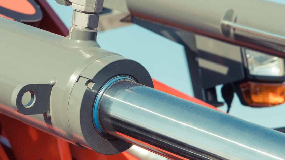
following problem statement. Please refer to the figure for a general feel for the actuator.
Problem statement: Design a hydraulic actuator (a.k.a. hydraulic cylinder) with a working stroke of
600 mm and a force capability of at least 100 kN in either direction and over the full stroke. A life of
no more than 10,000 complete cycles (full stroke in each direction) is anticipated. Cost must be kept to
a minimum and this unit will be used only in small quantities. Weight is not a major issue. Assume
that the hydraulic oil supply and control system is available with the oil having a controlled pressure
range of 0 to 10 MPa. Actuator force must be co-axial with the center line of the actuator and no
bending moment should be induced in the actuator. At one end of the actuator provide a bracket to bolt
to a flat steel surface (this surface could be at any angle within ±90° of the actuator axis.
Work as part of your assigned design group. In the final report submit the following (due 01 July
2024):
- Drawings of the final design
- Parts list
- Raw materials list
- Complete calculations for the final design
- Description of the design process including all assumptions.
Note that if an “off-the-shelf” actuator can be located, the customer will be quite happy since this will
save production costs and cut procurement time. However, if such an actuator is chosen, the
requirements of the report as listed above are not obviated. In addition, the vendor name and address,
part number, cost of the actuator, and availability will also be required. Calculations must also be
included to show that the design will meet the requirements of the problem statement (that is, show that
the manufacturer’s specifications will provide the necessary performance . (at a minimum, confirm the
pressure vessel integrity of the cylinder, the maximum push/pull capacity of the piston, and the
yield/buckling capability of the push/pull rod).
1. Understand the Problem Statement
Before jumping into the design process, make sure you are thoroughly familiar with the problem statement. Here’s a quick summary:
- Working Stroke: 600 mm
- Force Capability: At least 100 kN in either direction over the full stroke
- Cycle Life: No more than 10,000 complete cycles
- Cost: Must be kept to a minimum
- Weight: Not a major issue
- Hydraulic Oil Supply: Controlled pressure range of 0 to 10 MPa
- Co-axial Force: Ensure no bending moment
- Mounting Bracket: Provide at one end to bolt to a flat steel surface (angle within ±90° of the actuator axis)
2. Start with Preliminary Drawings
Begin by sketching out preliminary designs. Use the provided figure as a reference for the general feel of the actuator. Your drawings should include:
- The actuator’s dimensions
- Placement of the mounting bracket
- Position of the hydraulic connections
All the drawings have been made on SolidWorks and Moving parts. In case you need, Simulation, It will be provided.
3. Compile a Parts List
List all the components required for the actuator, including:
- Cylinder body
- Piston
- Rod
- Seals
- Mounting bracket
- Hydraulic fittings
All parts meet the specified force and pressure requirements.
4. Select Raw Materials
Choose materials that can withstand the operating conditions. Consider:
5. Perform Complete Calculations
To ensure the hydraulic actuator performs as required, conduct thorough calculations:
6. Explore Off-the-Shelf Options
Check if an off-the-shelf actuator meets the requirements. This can save production costs and cut procurement time. If found, include:
- Vendor name and address
- Part number
- Cost and availability
- Verification calculations showing it meets the problem statement requirements
7. Document the Design Process
In your final report, provide a detailed description of the design process. This should include:
- All assumptions and rationale behind design decisions
- Challenges faced and how they were resolved
- Any iterations and modifications made during the design phase
8. Submit the Final Report
Prepare your final report, which should include:
- Comprehensive drawings of the final design
- A complete parts list
- A raw materials list
- All calculations
- A detailed design process description
The due date for the final report is July 1, 2024. Ensure that all the elements are meticulously documented and presented clearly.
Want To Buy?
Designing an efficient and cost-effective hydraulic actuator requires thorough understanding and meticulous planning. By following these steps, we have completed the final design that meets the customer’s needs and adheres to the problem statement. Let’s get started and create something exceptional for Advanced Hydraulics Inc!
Feel free to reach out if you have any questions or need the complete design and everything related to this project. Good luck, team!


